Projekt Arduino – urządzenie do biofeedbacku – nauka medytacji – część 2 – podłączenie żyroskopu
Jeśli jesteś tu po raz pierwszy, zachęcam do zapoznania się z poprzednią częścią – która jest swego rodzaju wprowadzeniem – takim opisem projektu i jego genezy.
Ponieważ na moje Arduino nano muszę poczekać, postanowiłam zacząć od Arduino Uno, które to „mam na stanie”. Poza tym, jest ono większe i łatwiej na nim prototypować i podłączać te wszystkie magiczne kabelki 🙂
Początek – w poszukiwaniu „jak to zrobić” 🙂
Dokumentacja do modułu GY-521 jest dostępna tutaj.
Ponieważ już baaardzo dawno nie miałam styczności z dokumentacją elektroniczną postanowiłam poszukać bardziej „łopatologicznych” opisów. Na szczęście internet przyszedł z pomocą i szybko znalazłam jak wszystko ze sobą połączyć. Google mocno w użyciu :). Co ciekawe, znajdowałam oprócz schematu również programy do obsługi modułu – ale o tym za chwilę.
Łączymy kabelki
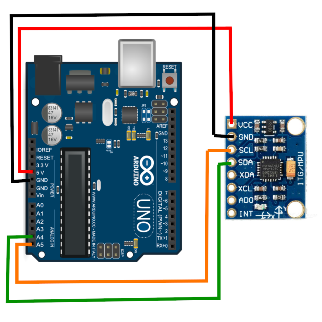
Tak wygląda schemat połączenia modułu GY-521 z Arduino:
A tak wygląda to u mnie z wykorzystaniem płytki prototypowej:
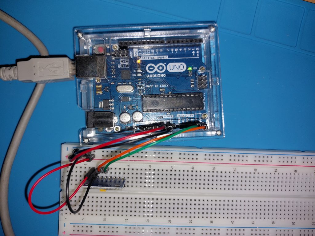
Notka nt. płytki prototypowej
Ponieważ wcześniej nie robiłam nic z Arduino, nie bardzo wiedziałam jak działa płytka prototypowa. Mniej-więcej się domyślałam tak na chłopski rozum, ale sprawdziłam miernikiem, które elementy są ze sobą pozwierane i to potwierdziło moje domysły – zwarte są ze sobą rzędy, np. u mnie „f-g-h-i-j” jest w każdym rzędzie zwarte, więc jak włożyłam mój moduł żyroskopu do kolumny „j”, to kabelki mogłam wpiąć w odpowiednie rzędy wyprowadzeń w kolumnie „g”. Dodatkowo cała kolumna + jest zwarta (użyłam jej jako źródła zasilania „+V”) i analogicznie kolumna „-” (użyłam jej jako masy „GND”)
Pora na program do zbierania danych przez USB
Tutaj nie ściemniam. Nie miałam pojęcia jak się zabrać za programowanie Arduino (mimo, że jako-tako programować potrafię). Dlatego skorzystałam z gotowca, po czym go przeanalizowałam ze zrozumieniem 🙂 i troszkę pozmieniałam to co wypisuje.
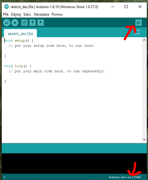
Ale zanim program, to trzeba zainstalować na komputerze środowisko Arduino IDE – jest ono darmowe i można je pobrać tutaj. Po uruchomieniu wygląda ono mniej więcej tak jak na poniższym zrzucie ekranu. Zaznaczyłam tam dwa punkty – prawy górny róg to przycisk do otworzenia „Monitora portu szeregowego”, natomiast w prawym dolnym rogu widać podłączone urządzenie (i port na którym się podłączyło).
Teraz wystarczy program. Mój, po przeróbkach oryginalu wyglada tak:
#include <Wire.h>
const int MPU_ADDR=0x68;
int16_t AcX, AcY, AcZ; // acc raw data
int16_t GyX, GyY, GyZ; // gyro raw data
int16_t Tmp; // temperature data

//for calc. roll, pitch and yaw
float accAngleX, accAngleY, gyroAngleX, gyroAngleY, gyroAngleZ;
float elapsedTime, currentTime, previousTime;
//float rollZ, pitchX, yawY; // Z- looking direction, Y- up/down, X-horizontal through ears
float rotZ, rotX, rotY; // Z- looking direction, Y- up/down, X-horizontal through ears

// varables for calc. error
float AcXerr, AcYerr, AcZerr; // acc error
float GyXerr, GyYerr, GyZerr; // gyro error
int c;

char tmp_str[7]; // temporary variable used in convert function
char* convert_int16_to_str(int16_t i) { // convert int16 to string - for debug window
  sprintf(tmp_str, "%6d", i);
  return tmp_str;
}

void setup() {

  // start transmission
  Serial.begin(9600);
  Serial.println("setup..");

  // put your setup code here, to run once:
  Wire.begin();
  Wire.beginTransmission(MPU_ADDR); // Begins a transmission to the I2C slave (GY-521 board)
  Wire.write(0x6B); //PWR_MGMT_1 register
  Wire.write(0); // set to zero (wakes up the MPU-6050)
  Wire.endTransmission(true);

  // do below at the beginning to check the errors that need to go to loop() equations
  // comment everything from the loop to have clear output
  //calculate_IMU_error(); //zero!! GyXerr = 0.12, GyYerr=1.30, GyZerr=0.32;
  //delay(500);
}

void loop() {
  // put your main code here, to run repeatedly:
  Wire.beginTransmission(MPU_ADDR);
  Wire.write(0x3B); // starting with reg. 0x38 (ACCEL_XOUT_H) [MPU-6000 and MPU-6050 Register Map and Descriptions Revision 4.2, p.40]
  Wire.endTransmission(false); // the parameter indicates that the Arduino will send a restart. As a result, the connection is kept active.
  Wire.requestFrom(MPU_ADDR, 7*2, true); // request a total of 7*2=14 registers
  // "Wire.read()<<8 | Wire.read();" means two registers are read and stored in the same variable
  AcX = Wire.read()<<8 | Wire.read(); // reading registers: 0x3B (ACCEL_XOUT_H) and 0x3C (ACCEL_XOUT_L)
  AcY = Wire.read()<<8 | Wire.read(); // reading registers: 0x3D (ACCEL_YOUT_H) and 0x3E (ACCEL_YOUT_L)
  AcZ = Wire.read()<<8 | Wire.read(); // reading registers: 0x3F (ACCEL_ZOUT_H) and 0x40 (ACCEL_ZOUT_L)
  Tmp = Wire.read()<<8 | Wire.read(); // reading registers: 0x41 (TEMP_OUT_H) and 0x42 (TEMP_OUT_L)
  GyX = Wire.read()<<8 | Wire.read(); // reading registers: 0x43 (GYRO_XOUT_H) and 0x44 (GYRO_XOUT_L)
  GyY = Wire.read()<<8 | Wire.read(); // reading registers: 0x45 (GYRO_YOUT_H) and 0x46 (GYRO_YOUT_L)
  GyZ = Wire.read()<<8 | Wire.read(); // reading registers: 0x47 (GYRO_ZOUT_H) and 0x48 (GYRO_ZOUT_L)


  //clclulate useful data
  previousTime = currentTime;        // Previous time is stored before the actual time read
  currentTime = millis();            // Current time actual time read
  elapsedTime = (currentTime - previousTime) / 1000; // Divide by 1000 to get seconds

  // Correct the outputs with the calculated error values
  GyX = GyX + 0.1; // GyroErrorX ~(0.12)
  GyY = GyY + 1.35; // GyroErrorY ~(1.30)
  GyZ = GyZ + 0.32; // GyroErrorZ ~ (0.32)

  accAngleX = (atan(AcY / sqrt(pow(AcX, 2) + pow(AcZ, 2))) * 180 / PI) - 0.0; // AccErrorX ~(0.0) See the calculate_IMU_error()custom function for more details
  accAngleY = (atan(-1 * AcX / sqrt(pow(AcY, 2) + pow(AcZ, 2))) * 180 / PI) + 0.0; // AccErrorY ~(0.0)
  gyroAngleX = gyroAngleX + GyX * elapsedTime; // deg/s * s = deg
  gyroAngleY = gyroAngleY + GyY * elapsedTime;

  //float rotZ, rotX, rotY; // Z- looking direction, Y- up/down, X-horizontal through ears
  rotY =  (rotY + GyZ * elapsedTime);
  // Complementary filter - combine acceleromter and gyro angle values
  rotZ = (0.96 * gyroAngleX + 0.04 * accAngleX) ;
  rotX = (0.96 * gyroAngleY + 0.04 * accAngleY) ;


  // print data

  Serial.print("   AcX |    AcY |    AcZ | \n");
  Serial.print(convert_int16_to_str(AcX)); Serial.print(" | ");
  Serial.print(convert_int16_to_str(AcY)); Serial.print(" | ");
  Serial.print(convert_int16_to_str(AcZ)); Serial.print(" | \n");
  // the following equation was taken from the documentation [MPU-6000/MPU-6050 Register Map and Description, p.30]
  Serial.print("---------------------------\n");
  Serial.print("   GyX |    GyY |    GyZ | \n");
  Serial.print(convert_int16_to_str(GyX)); Serial.print(" | ");
  Serial.print(convert_int16_to_str(GyY)); Serial.print(" | ");
  Serial.print(convert_int16_to_str(GyZ)); Serial.print(" | \n");
  Serial.print("---------------------------\n");
  Serial.print("Tmp = ");Serial.print(Tmp/340.00+36.53); Serial.print("\n");
  Serial.print("---------------------------\n");
  Serial.print("  RotX |   RotY |   RotZ | \n");
  Serial.print(rotX); Serial.print(" | ");
  Serial.print(rotY); Serial.print(" | ");
  Serial.print(rotZ); Serial.print(" | \n");
  Serial.print("---------------------------\n");

  Serial.print("\n");

  //delay
  delay(20);
}

void calculate_IMU_error() {
  // We can call this funtion in the setup section to calculate the accelerometer and gyro data error. From here we will get the error values used in the above equations printed on the Serial Monitor.
  // Note that we should place the IMU flat in order to get the proper values, so that we then can the correct values
  // Read accelerometer values 200 times
  const int NUM_TRIES = 200;
  while (c < NUM_TRIES) {
    Wire.beginTransmission(MPU_ADDR);
    Wire.write(0x3B);
    Wire.endTransmission(false);
    Wire.requestFrom(MPU_ADDR, 3*2, true);
    AcX = (Wire.read() << 8 | Wire.read()) / 16384.0 ;
    AcY = (Wire.read() << 8 | Wire.read()) / 16384.0 ;
    AcZ = (Wire.read() << 8 | Wire.read()) / 16384.0 ;
    // Sum all readings
    AcXerr = AcXerr + ((atan((AcY) / sqrt(pow((AcX), 2) + pow((AcZ), 2))) * 180 / PI));
    AcYerr = AcYerr + ((atan(-1 * (AcX) / sqrt(pow((AcY), 2) + pow((AcZ), 2))) * 180 / PI));
    c++;
  }
  //Divide the sum by 200 to get the error value
  AcXerr = AcXerr / NUM_TRIES;
  AcYerr = AcYerr / NUM_TRIES;
  c = 0;
  // Read gyro values 200 times
  while (c < NUM_TRIES) {
    Wire.beginTransmission(MPU_ADDR);
    Wire.write(0x43);
    Wire.endTransmission(false);
    Wire.requestFrom(MPU_ADDR, 3*2, true);
    GyX = Wire.read() << 8 | Wire.read();
    GyY = Wire.read() << 8 | Wire.read();
    GyZ = Wire.read() << 8 | Wire.read();
    // Sum all readings
    GyXerr = GyXerr + (GyX / 131.0);
    GyYerr = GyYerr + (GyY / 131.0);
    GyZerr = GyZerr + (GyZ / 131.0);
    c++;
  }
  //Divide the sum by 200 to get the error value
  GyXerr = GyXerr / NUM_TRIES;
  GyYerr = GyYerr / NUM_TRIES;
  GyZerr = GyZerr / NUM_TRIES;
  // Print the error values on the Serial Monitor
  Serial.print("AcXerr: ");
  Serial.println(AcXerr);
  Serial.print("AcYerr: ");
  Serial.println(AcYerr);
  Serial.print("GyXerr: ");
  Serial.println(GyXerr);
  Serial.print("GyYerr: ");
  Serial.println(GyYerr);
  Serial.print("GyZerr: ");
  Serial.println(GyZerr);
}
No i voual’a! Mam odczyty!
Uwaga do odczytów: zanim uruchomiłam główny program, położyłam sensor nieruchomo oraz odpaliłam tylko funkcję calculate_IMU_error(). Ona zbiera 200 odczytów (można to zmienić ustawiając wartość NUM_TRIES), uśrednia je i pokazuje wynik – jest to tak naprawdę błąd sensora (czyli taka kalibracja). Należy ten błąd uwzględnić w programie w obliczeniach:
GyX = GyX + 0.1; // GyroErrorX ~(0.12)
GyY = GyY + 1.35; // GyroErrorY ~(1.30)
GyZ = GyZ + 0.32; // GyroErrorZ ~ (0.32)

accAngleX = (atan(AcY / sqrt(pow(AcX, 2) + pow(AcZ, 2))) * 180 / PI) - 0.0; // AccErrorX ~(0.0) See the calculate_IMU_error()custom function for more details

accAngleY = (atan(-1 * AcX / sqrt(pow(AcY, 2) + pow(AcZ, 2))) * 180 / PI) + 0.0; // AccErrorY ~(0.0)
Notka nt. Arduino IDE i VS Code
Ostatnio większość programów pisałam w Visual Studio Code i bardzo lubię to IDE. Dlatego szukałam jak użyć mojego ulubionego środowiska do Arduino – no i jak się domyślacie znalazłam instrukcje tutaj (wersja po angielsku). Ale uwaga! To nie zadziała jeśli macie zainstalowane Arduino IDE ze sklepu Microsoft (pod Windowsem oczywiście). Ja tak miałam i musiałam odinstalować to ze sklepu, ściągnąć wersję dla Win7+, zainstalować i wtedy zadziałało (trzeba jeszcze w konfiguracji płytki podać ścieżkę do instalacji Arduino IDE – to właśnie był problem przy aplikacji ze sklepu – a może wiecie jak odnaleźć ścieżkę do apek ze sklepu Microsoftu? Napiszcie w komentarzach!
UPDATE: Niestety okazało się, że nie mogę zmusić „Serial monitora” do pokazywania danych na bieżąco i ostatecznie zrezygnowałam z VSCode na rzecz Arduino IDE 2.0.0-rec3, które oferuje uzupełnianie składni i jest dość podobne do VSCode.