Arduino Project – Biofeedback Device – Learning Meditation – Part 2 – Gyroscope Connection
If you are here for the first time, I encourage you to read the previous part – which is a kind of introduction – a description of the project and its genesis.
Since I have to wait for my Arduino nano, I decided to start with Arduino Uno, which “I have in stock”. Besides, it’s bigger and easier to prototype on it and connect all those magic cables 🙂
The beginning – in search of “how to do it” 🙂
Documentation for the GY-521 is available here.
Because I have not had contact with electronic documentation for a long time, I decided to look for more “human-understandable” descriptions. Fortunately, the Internet came to the rescue and I quickly found how to connect everything together. Google heavily in use :). Interestingly, in addition to the scheme, I also found programs to operate the module – but more on that in a moment.
We connect the cables
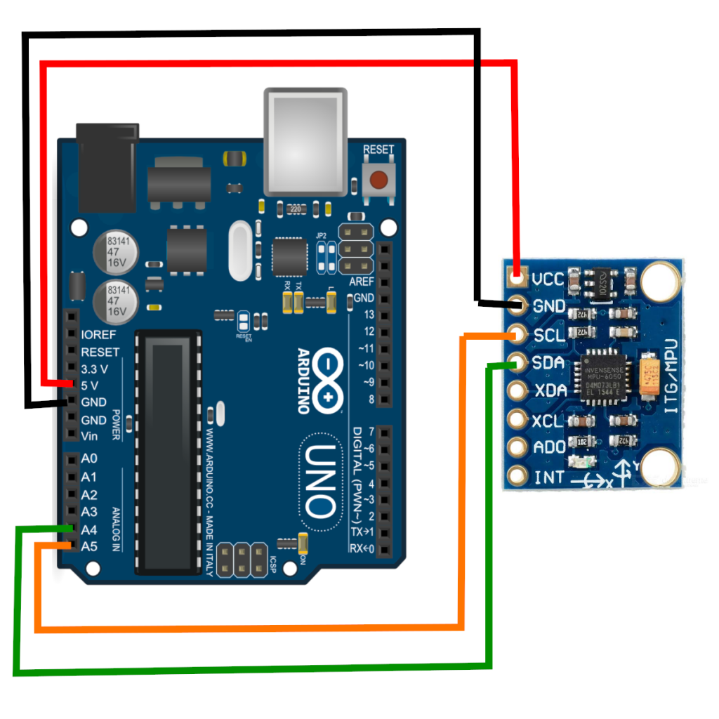
This is the connection diagram of the GY-521 module with Arduino:
And this is how it looks in my set-up – using the prototype board:
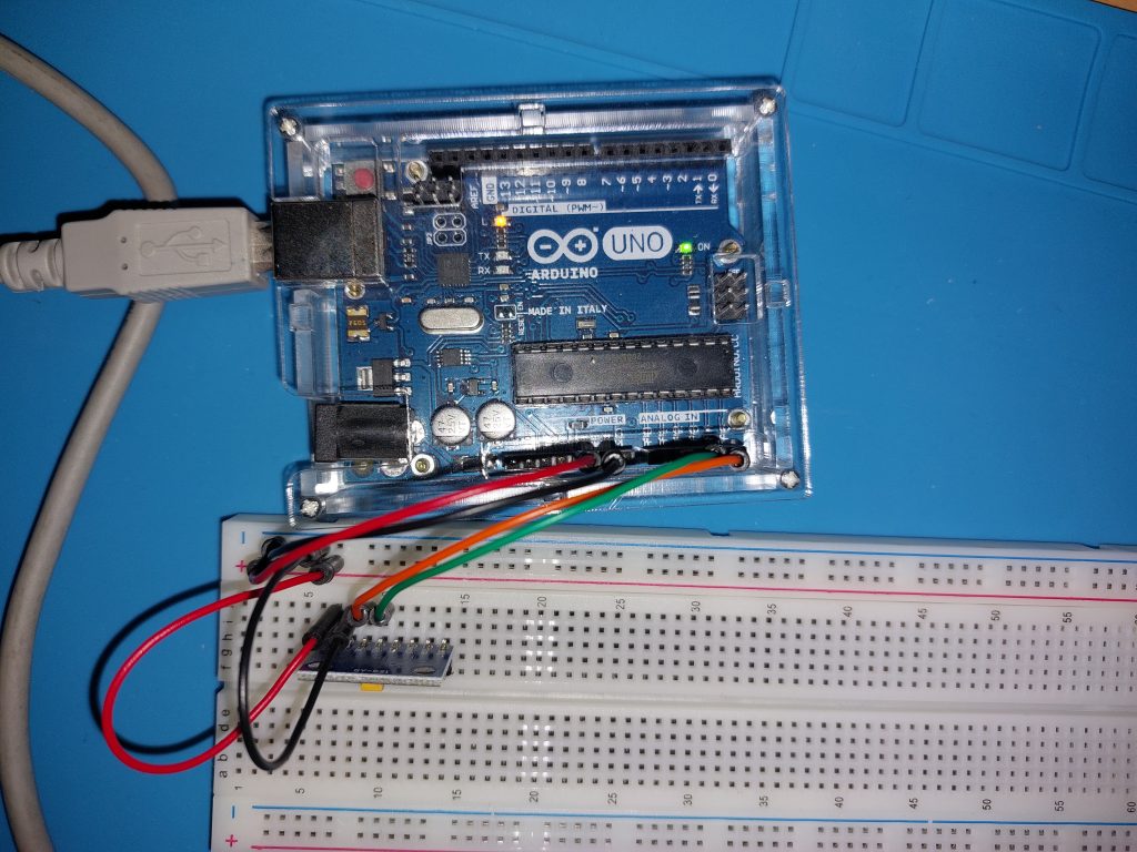
Note on the prototype board
Since I hadn’t done anything with Arduino before, I didn’t really know how the prototype board works. I more or less guessed it, but I at the end I checked with a electonic-meter which elements are connected to each other and this confirmed my guess – rows are connected with each other, e.g. in my case “f-g-h-i-j” is connected in each row, so when I inserted my gyroscope module into the “j” column, I could plug the cables into the appropriate rows of pins in the “g” column. In addition, the entire + column is short (I used it as a power source “+V”) and similarly the column “-” (I used it as a mass “GND”)
It’s time for a USB data collection program
Here I do not darken. I had no idea how to start programming Arduino (even though I can program as such). That’s why I used the ready-made, and then analyzed it with the understanding of 🙂 and A little changed what he writes.
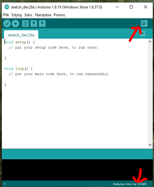
But before the program, then you need to install on your computer the Arduino IDE environment – it is free and you can download it here. When launched, it looks more or less like the screenshot below. I marked two points there – the upper right corner is the button to open the “Serial Port Monitor”, while in the lower right corner you can see the connected device (and the port on which you connected).
Now all you need is the program. Mine, after altering the original looks like this:
<Wire.h>#include
const int MPU_ADDR=0x68;
int16_t AcX, AcY, AcZ; acc raw date
int16_t GyX, GyY, GyZ; gyro raw date
Tmp int16_t; temperature date

for calc. roll, pitch and yaw
float accAngleX, accAngleY, gyroAngleX, gyroAngleY, gyroAngleZ;
float elapsedTime, currentTime, previousTime;
float rollZ, pitchX, yawY; Z- looking direction, Y- up/down, X-horizontal through ears
float rotZ, rotX, roty; Z- looking direction, Y- up/down, X-horizontal through ears

varables for calc. error
float AcXerr, AcYerr, AcZerr; acc error
float GyXerr, GyYerr, GyZerr; gyro error
int c;

char tmp_str [7] ; // temporary variable used in convert function
char* convert_int16_to_str(int16_t i) { // convert int16 to string - for debug window
  sprintf(tmp_str, "%6d", i);
  return tmp_str;
}

void setup() {

start transmission
  Serial.begin(9600);
  Serial.println("setup..");</Wire.h>

  put your setup code here, to run once:
  Wire.begin();
  Wire.beginTransmission(MPU_ADDR); Begins a transmission to the I2C slave (GY-521 board)
  Wire.write(0x6B); PWR_MGMT_1 register
  Wire.write(0); set to zero (wakes up the MPU-6050)
  Wire.endTransmission(true);

do below at the beginning to check the errors that need to go to loop() equations
  comment everything from the loop to have clear output
  calculate_IMU_error(); zero!! GyXerr = 0.12, GyYerr=1.30, GyZerr=0.32;
  delay(500);
}

void loop() {
  put your main code here, to run repeatedly:
  Wire.beginTransmission(MPU_ADDR);
  Wire.write(0x3B); starting with reg. 0x38 (ACCEL_XOUT_H) [MPU-6000 and MPU-6050 Register Map and Descriptions Revision 4.2, p.40]
  Wire.endTransmission(false); the parameter indicates that the Arduino will send a restart. As a result, the connection is kept active.
  Wire.requestFrom(MPU_ADDR, 7*2, true); request a total of 7 * 2 = 14 registers
  "Wire.read() <8 | Wire.read();" means two registers are read and stored in the same variable
  AcX = Wire.read() <8 | Wire.read(); // reading registers: 0x3B (ACCEL_XOUT_H) and 0x3C (ACCEL_XOUT_L)
  AcY = Wire.read() <8 | Wire.read(); // reading registers: 0x3D (ACCEL_YOUT_H) and 0x3E (ACCEL_YOUT_L)
  AcZ = Wire.read() <8 | Wire.read(); // reading registers: 0x3F (ACCEL_ZOUT_H) and 0x40 (ACCEL_ZOUT_L)
  Tmp = Wire.read() <8 | Wire.read(); // reading registers: 0x41 (TEMP_OUT_H) and 0x42 (TEMP_OUT_L)
  GyX = Wire.read() <8 | Wire.read(); // reading registers: 0x43 (GYRO_XOUT_H) and 0x44 (GYRO_XOUT_L)
  GyY = Wire.read() <8 | Wire.read(); // reading registers: 0x45 (GYRO_YOUT_H) and 0x46 (GYRO_YOUT_L)
  GyZ = Wire.read() <8 | Wire.read(); // reading registers: 0x47 (GYRO_ZOUT_H) and 0x48 (GYRO_ZOUT_L)


  //clclulate useful data
  previousTime = currentTime;        // Previous time is stored before the actual time read
  currentTime = millis();            // Current time actual time read
  elapsedTime = (currentTime - previousTime) / 1000; // Divide by 1000 to get seconds

  // Correct the outputs with the calculated error values
  GyX = GyX + 0.1; // GyroErrorX ~(0.12)
  GyY = GyY + 1.35; // GyroErrorY ~(1.30)
  GyZ = GyZ + 0.32; // GyroErrorZ ~ (0.32)

  accAngleX = (atan(AcY / sqrt(pow(AcX, 2) + pow(AcZ, 2))) * 180 / PI) - 0.0; // AccErrorX ~(0.0) See the calculate_IMU_error()custom function for more details
  accAngleY = (atan(-1 * AcX / sqrt(pow(AcY, 2) + pow(AcZ, 2))) * 180 / PI) + 0.0; // AccErrorY ~(0.0)
  gyroAngleX = gyroAngleX + GyX * elapsedTime; // deg/s * s = deg
  gyroAngleY = gyroAngleY + GyY * elapsedTime;

  //float rotZ, rotX, rotY; // Z- looking direction, Y- up/down, X-horizontal through ears
  rotY =  (rotY + GyZ * elapsedTime);
  // Complementary filter - combine acceleromter and gyro angle values
  rotZ = (0.96 * gyroAngleX + 0.04 * accAngleX) ;
  rotX = (0.96 * gyroAngleY + 0.04 * accAngleY) ;


  // print data

  Serial.print("   AcX |    AcY |    AcZ | n");
  Serial.print(convert_int16_to_str(AcX)); Serial.print(" | ");
  Serial.print(convert_int16_to_str(AcY)); Serial.print(" | ");
  Serial.print(convert_int16_to_str(AcZ)); Serial.print(" | n");
  // the following equation was taken from the documentation  [MPU-6000/MPU-6050 Register Map and Description, p.30]
  Serial.print("---------------------------n");
  Serial.print(" GyX |    GyY |    GyZ | n");
  Serial.print(convert_int16_to_str(GyX)); Serial.print(" | ");
  Serial.print(convert_int16_to_str(GyY)); Serial.print(" | ");
  Serial.print(convert_int16_to_str(GyZ)); Serial.print(" | n");
  Serial.print("---------------------------n");
  Serial.print("Tmp = "); Serial.print(Tmp/340.00+36.53); Serial.print("n");
  Serial.print("---------------------------n");
  Serial.print(" RotX |   RotY |   RotZ | n");
  Serial.print(rotX); Serial.print(" | ");
  Serial.print(rotY); Serial.print(" | ");
  Serial.print(rotZ); Serial.print(" | n");
  Serial.print("---------------------------n");

Serial.print("n");

delay
  delay(20);
}

void calculate_IMU_error() {
  We can call this funtion in the setup section to calculate the accelerometer and gyro data error. From here we will get the error values used in the above equations printed on the Serial Monitor.
  Note that we should place the IMU flat in order to get the proper values, so that we then can the correct values
  Read accelerometer values 200 times
  const int NUM_TRIES = 200;
  while (c < NUM_TRIES) {
    Wire.beginTransmission(MPU_ADDR);
    Wire.write(0x3B);
    Wire.endTransmission(false);
    Wire.requestFrom(MPU_ADDR, 3*2, true);
    AcX = (Wire.read() < 8 | Wire.read()) / 16384.0 ;
    AcY = (Wire.read() < 8 | Wire.read()) / 16384.0 ;
    AcZ = (Wire.read() < 8 | Wire.read()) / 16384.0 ;
    // Sum all readings
    AcXerr = AcXerr + ((atan((AcY) / sqrt(pow((AcX), 2) + pow((AcZ), 2))) * 180 / PI));
    AcYerr = AcYerr + ((atan(-1 * (AcX) / sqrt(pow((AcY), 2) + pow((AcZ), 2))) * 180 / PI));
    c++;
  }
  //Divide the sum by 200 to get the error value
  AcXerr = AcXerr / NUM_TRIES;
  AcYerr = AcYerr / NUM_TRIES;
  c = 0;
  // Read gyro values 200 times
  while (c < NUM_TRIES) {
    Wire.beginTransmission(MPU_ADDR);
    Wire.write(0x43);
    Wire.endTransmission(false);
    Wire.requestFrom(MPU_ADDR, 3*2, true);
    GyX = Wire.read() < 8 | Wire.read();
    GyY = Wire.read() < 8 | Wire.read();
    GyZ = Wire.read() < 8 | Wire.read();
    // Sum all readings
    GyXerr = GyXerr + (GyX / 131.0);
    GyYerr = GyYerr + (GyY / 131.0);
    GyZerr = GyZerr + (GyZ / 131.0);
    c++;
  }
  //Divide the sum by 200 to get the error value
  GyXerr = GyXerr / NUM_TRIES;
  GyYerr = GyYerr / NUM_TRIES;
  GyZerr = GyZerr / NUM_TRIES;
  // Print the error values on the Serial Monitor
  Serial.print("AcXerr: ");
  Serial.println(AcXerr);
  Serial.print("AcYerr: ");
  Serial.println(AcYerr);
  Serial.print("GyXerr: ");
  Serial.println(GyXerr);
  Serial.print("GyYerr: ");
  Serial.println(GyYerr);
  Serial.print("GyZerr: ");
  Serial.println(GyZerr);
}
And voual’a! I have readings!
Note to the readings: before I started the main program, I put the sensor still and fired only the calculate_IMU_error() function. It collects 200 readings (this can be changed by setting the value of NUM_TRIES), averages them and shows the result – this is really a sensor error (i.e. kind of a calibration). This error should be included in the program in the calculations:
GyX = GyX + 0.1; GyroErrorX ~(0.12)
GyY = GyY + 1.35; GyroErrorY ~(1.30)
GyZ = GyZ + 0.32; GyroErrorZ ~ (0.32)

accAngleX = (atan(AcY / sqrt(pow(AcX, 2) + pow(AcZ, 2))) * 180 / PI) - 0.0; See the calculate_IMU_error()custom function for more details

accAngleY = (atan(-1 * AcX / sqrt(pow(AcY, 2) + pow(AcZ, 2))) * 180 / PI) + 0.0; AccErrorY ~(0.0)
Note on Arduino IDE and VS Code
I’ve been writing most of my programs in Visual Studio Code lately, and I really like this IDE. That’s why I was looking for how to use my favorite environment for Arduino – and guess what – I found instructions here (English version). But beware! This will not work if you have installed the Arduino IDE from the Microsoft store (under Windows of course). I had it and I had to uninstall it from the store, download the version for Win7+, install it and then it worked (you still have to specify the path the Arduino IDE installation in the configuration of the board – this was the problem with the application from the MS store – or maybe you know how to find the path to the apps from the Microsoft store? Write in the comments!
UPDATE: Unfortunately, it turned out that I could not force the “Serial monitor” to show data on a regular basis and eventually gave up VSCode in favor of Arduino IDE 2.0.0-rec3, which offers syntax completion and is quite similar to VSCode.